- Installation
Installation
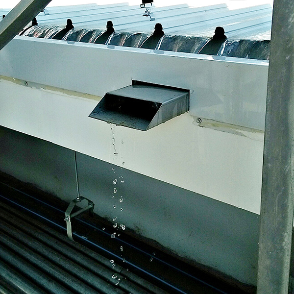
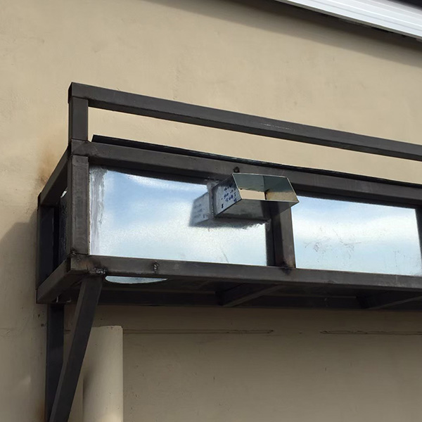
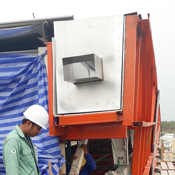
The method of installation of rainwater outlets depends on the gutter material. Gutter thickness should be at least 1.5 – 2 millimeters.
For Stainless steel gutter, installed by Argon-welding method
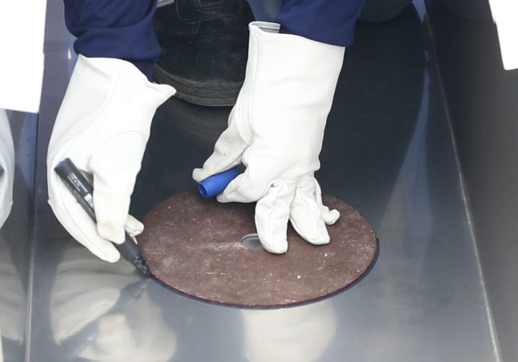
- Mark the position of rainwater outlet
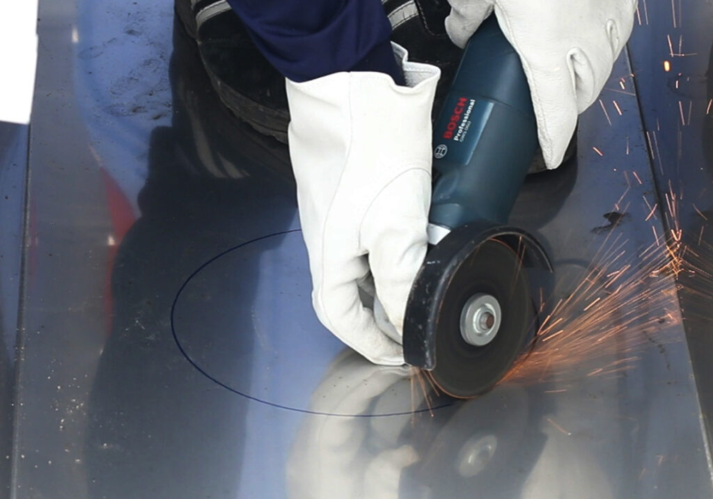
- Drill a 220 mm. hole
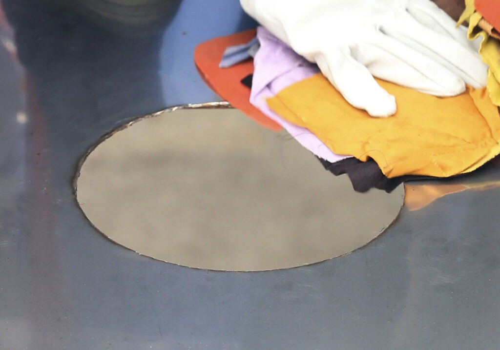
Wipe the gutter clean
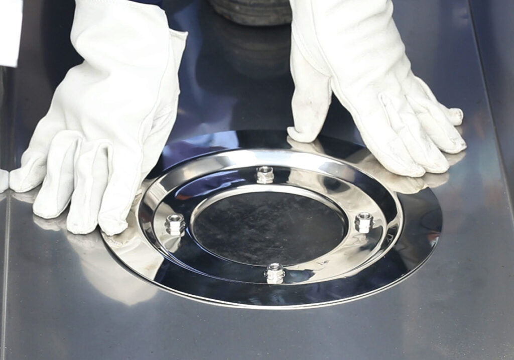
Place Spigot assembled with Adapter Flange on the hole
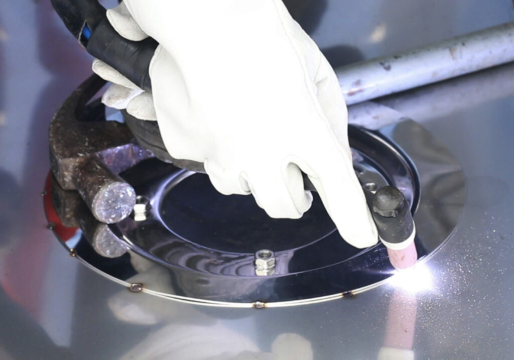
Weld Spigot all the way around to secure the position
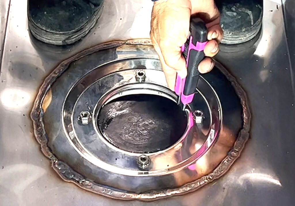
Slit the rubber gasket off
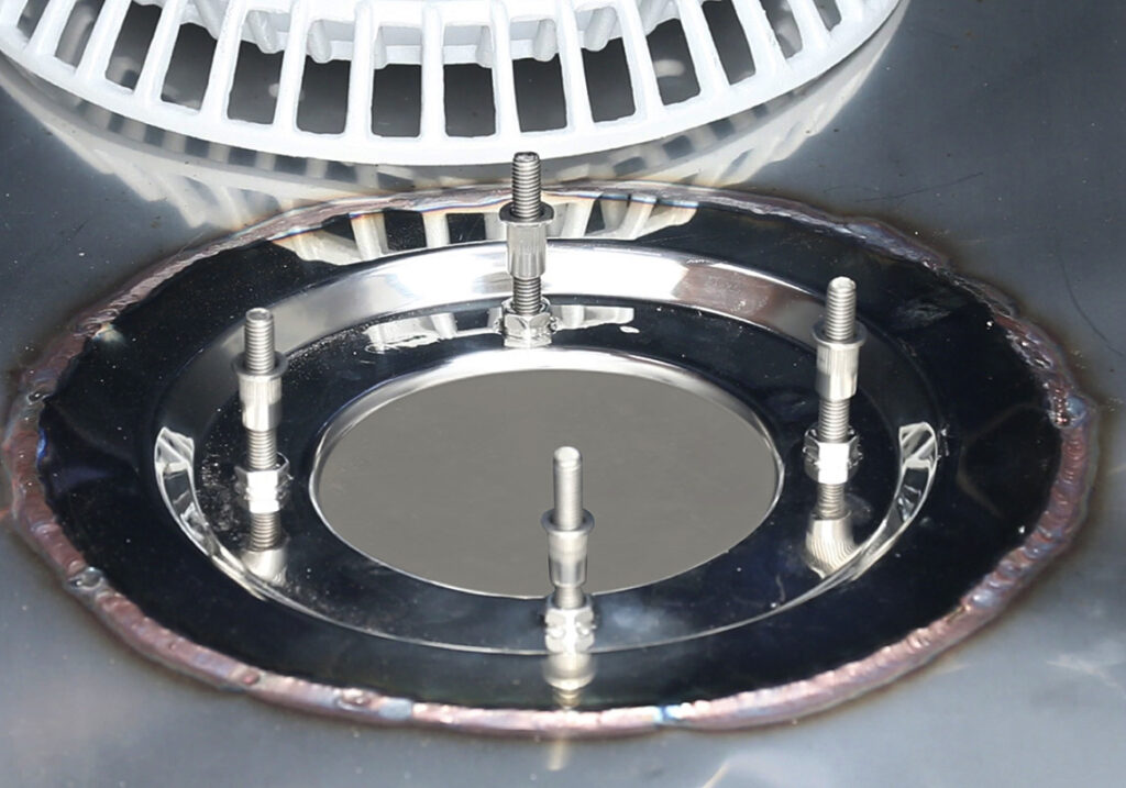
Install Stud Rod and Spacer at all 4 points
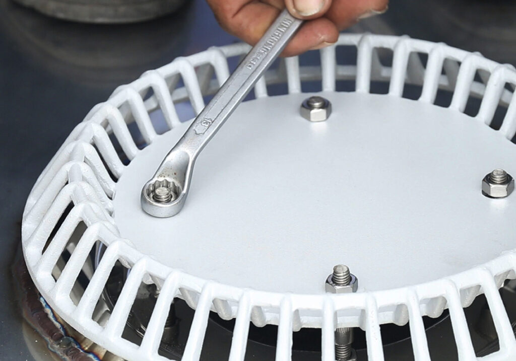
Install Anti-Vortex Plate and tighten the nut at all 4 points
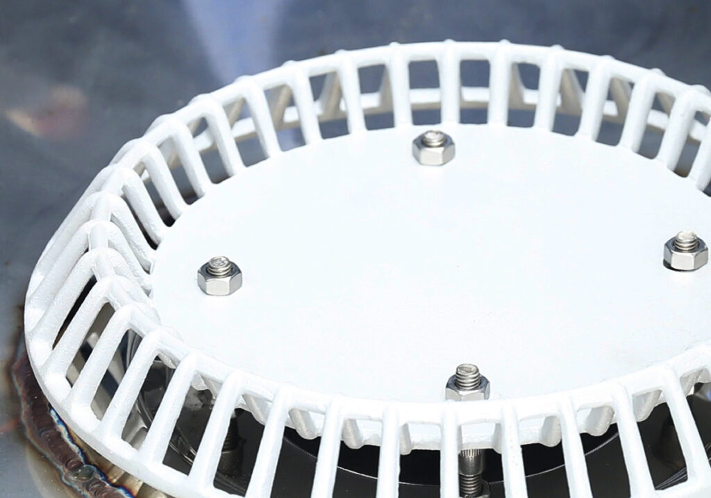
Installation complete
For steel gutter, installed by bolt and nut tightening method
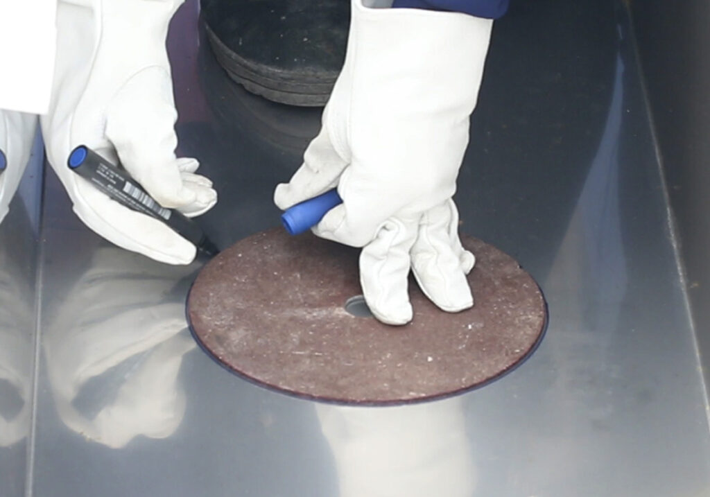
- Mark the position of rainwater outlet
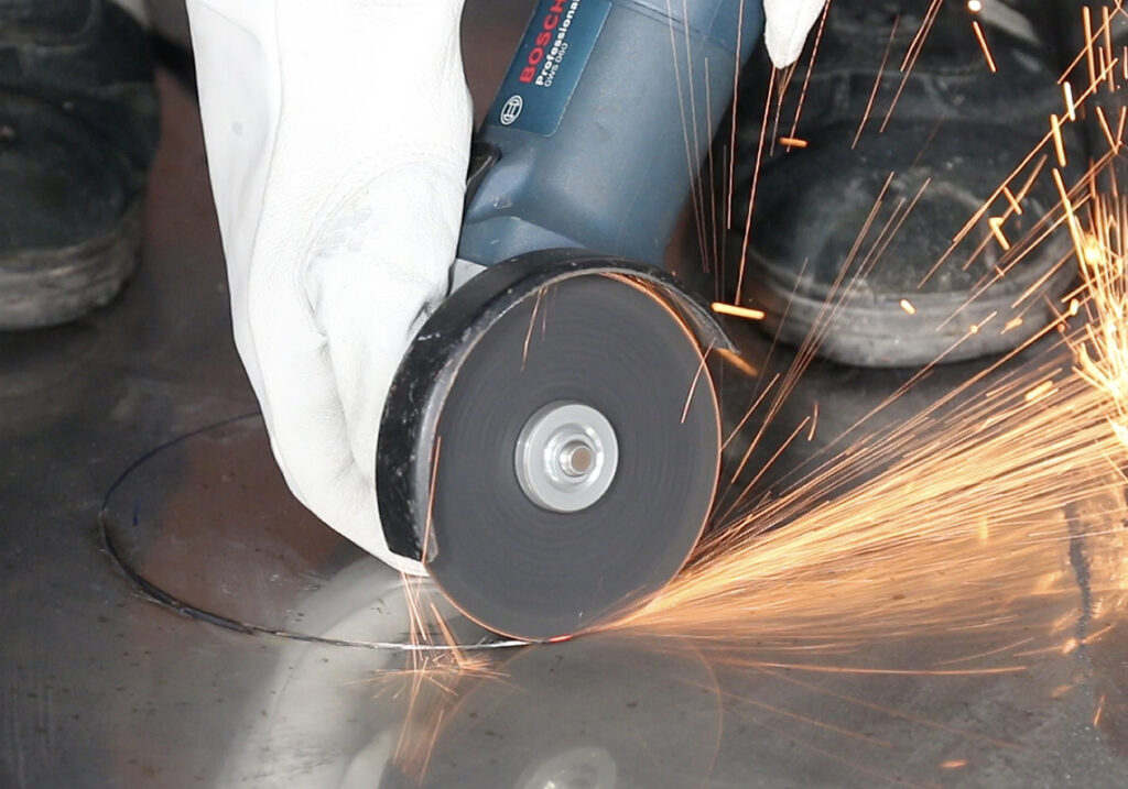
- Drill a 220 mm. hole
Wipe the gutter clean
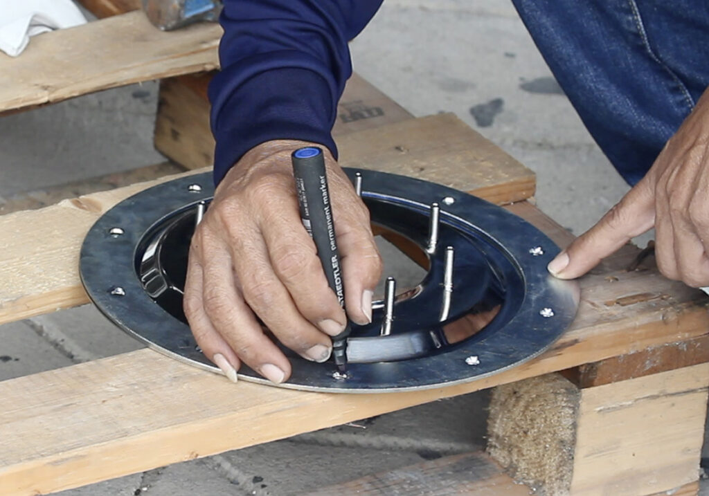
Mark the position by the holes on Backing Ring onto Spigot to all 10 points
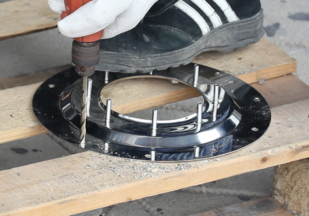
Drill holes on Spigot as marked for all 10 points
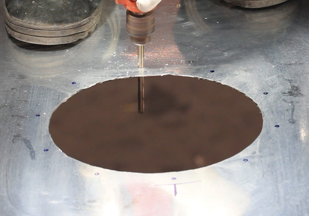
Place Spigot on the gutter, then mark the position on it, and drill all 10 holes
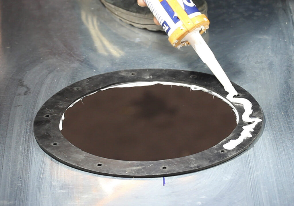
Caulk silicone sealant on the gutter, then place a rubber gasket and caulk it with silicone sealant again
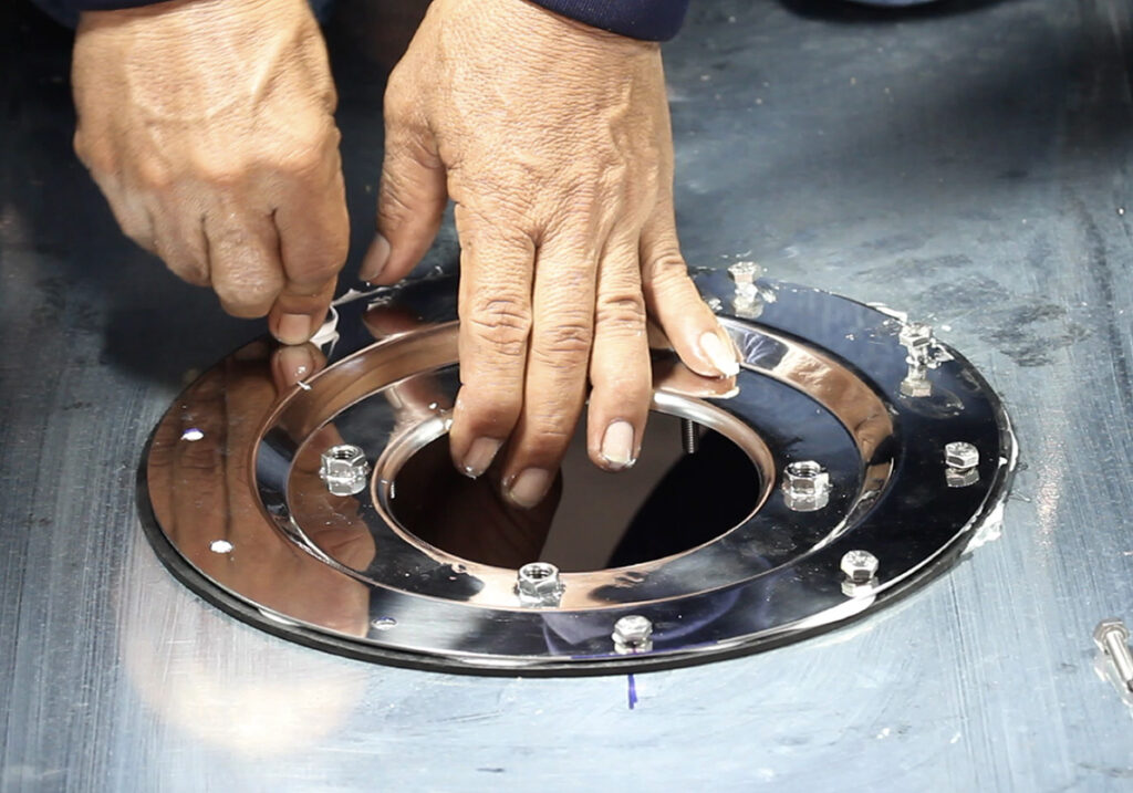
Place Spigot onto the rubber gasket, then install all 10 pieces of Bolt M6.
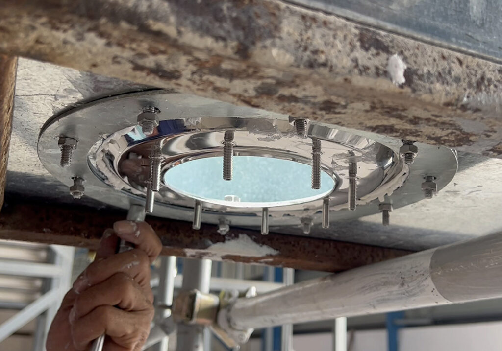
For underneath the gutter, install backing Ring, then tighten all 10 pieces of Nut M6
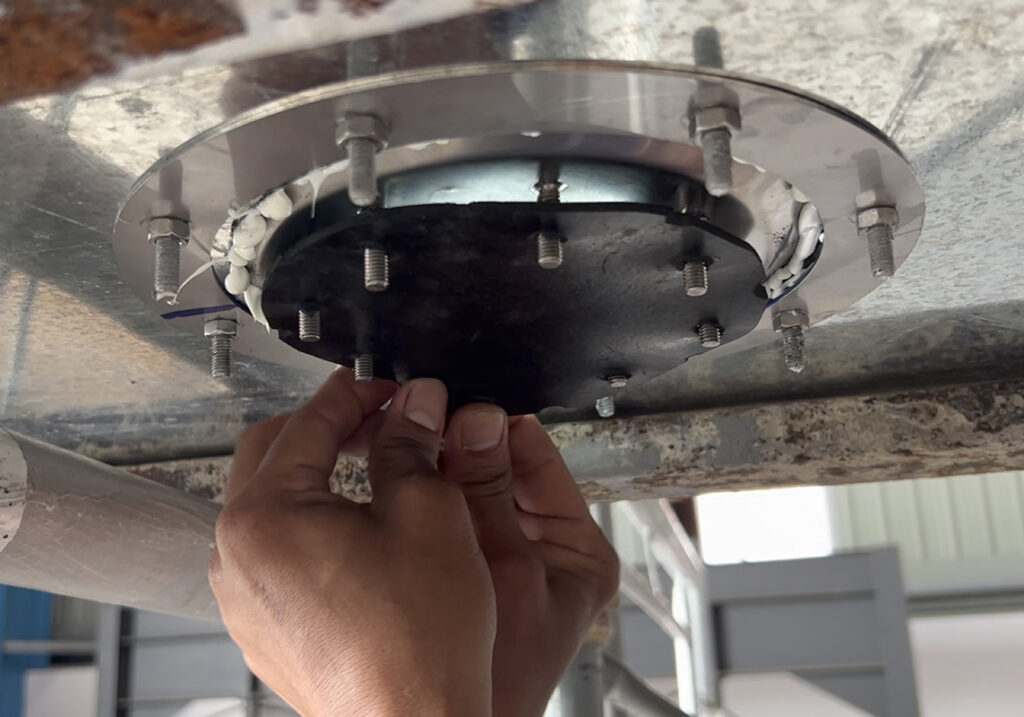
Install the rubber gasket
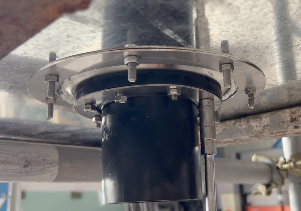
Install Adapter Flange followed by Backing Ring, then tighten Nut M6
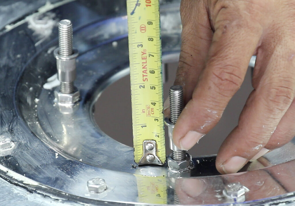
Install Stud Rod and Spacer for all 4 points (place Spacer higher from the Spigot base at least 3 cm.)
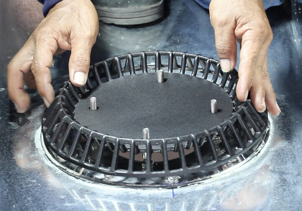
Install Anti-vortex
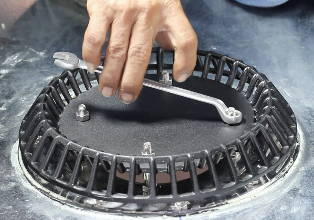
Tighten Nut M8 over all 4 points
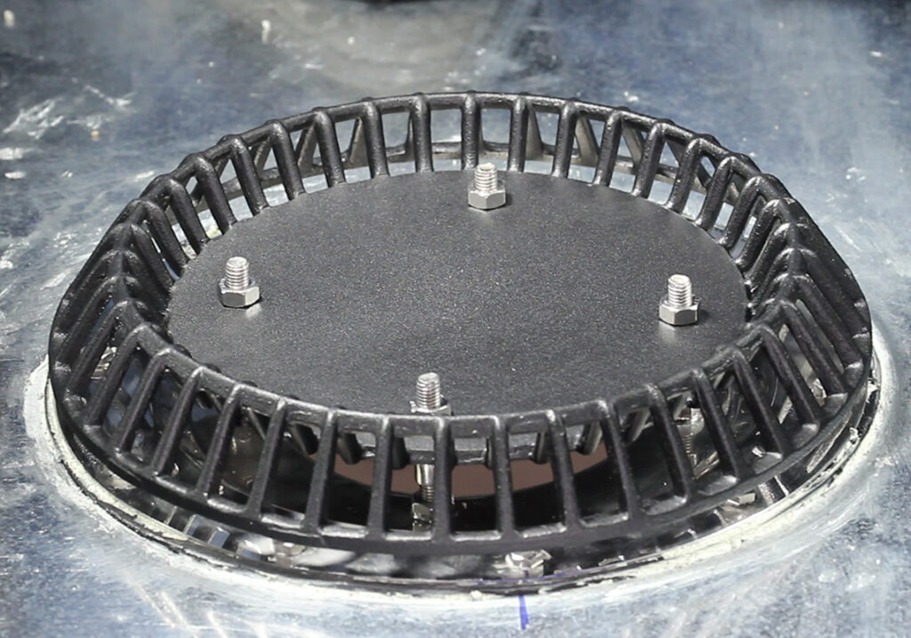
Installation complete
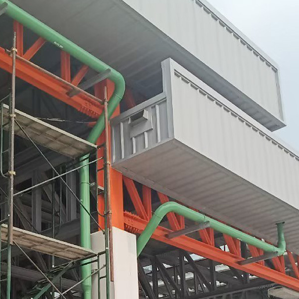
For concrete roof, installed by concrete embedment method
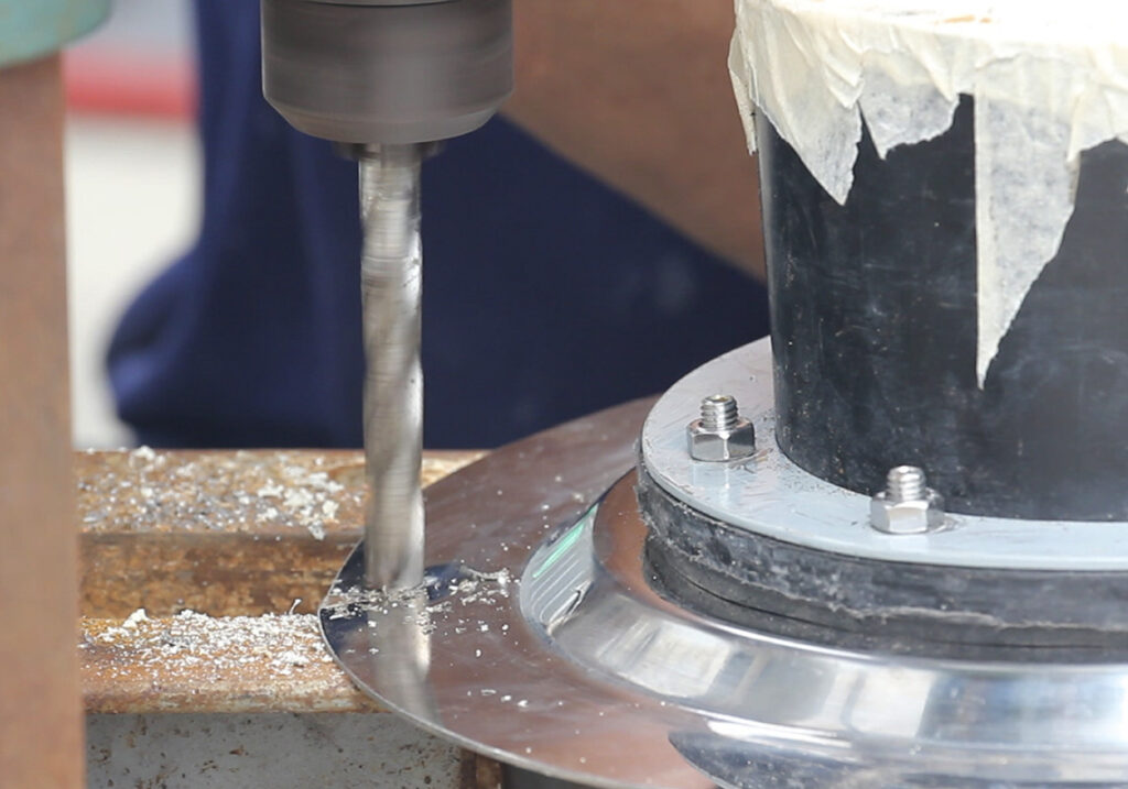
Drill a hole at Spigot’s wing for the threat of Stud Rod to secure the outlet’s position
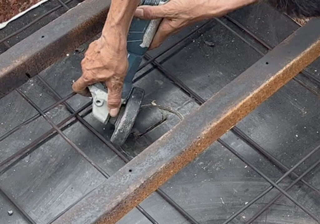
Drill a hole on shutter board to position the Sleeve
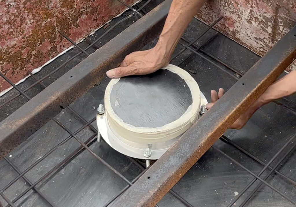
Place concrete outlet covered with plywood to prevent mortar fill-in, which can cause clogged downpipes
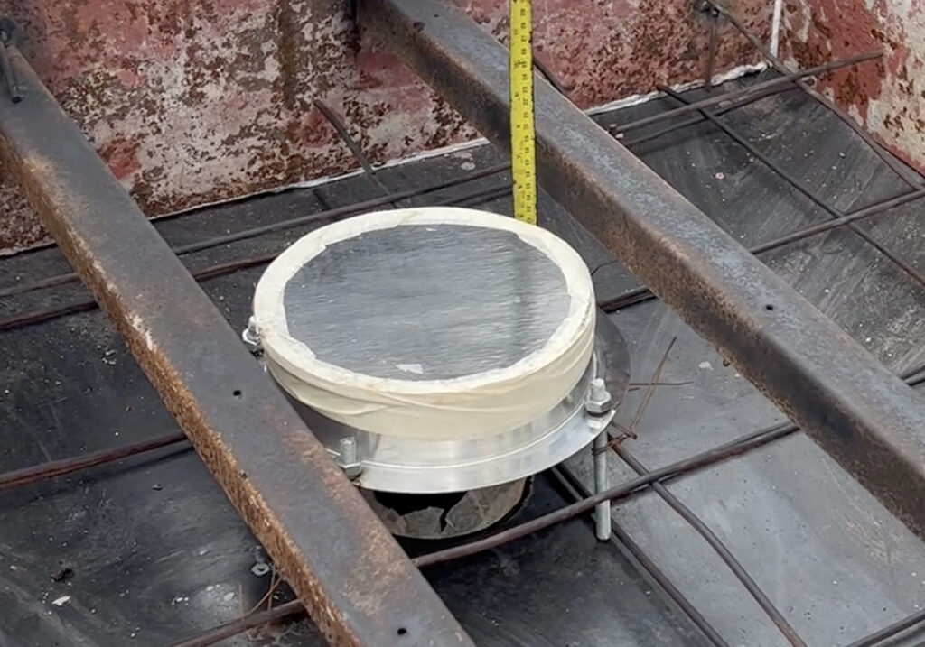
Set the outlet level with the top edge at the same height as Depressed Floor
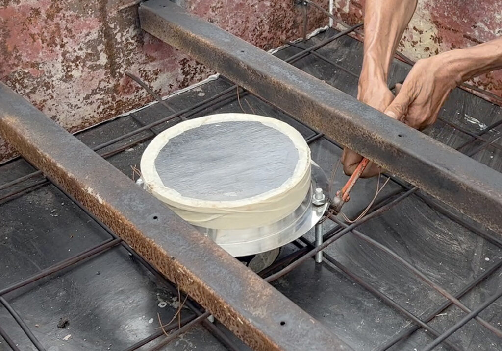
Tie the wire to secure the outlet’s position
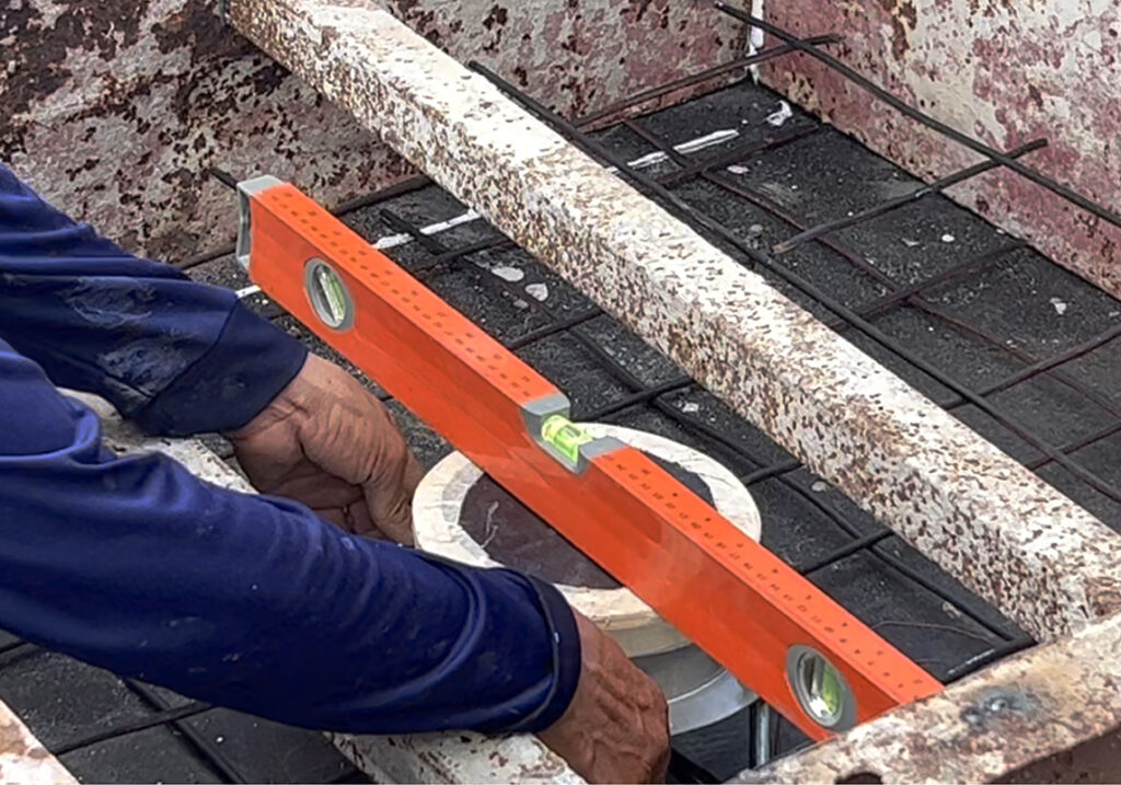
Use a horizontal level indicator (water level gauge ruler) to check the gradient and weld to secure position
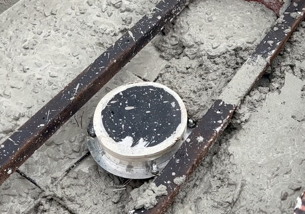
Concrete pouring and casting.
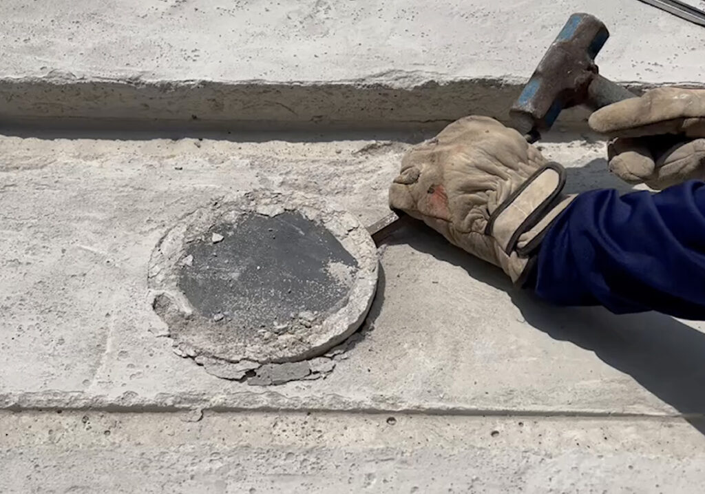
When the concrete is set and the rainwater drainage pipework is ready to use, remove the plywood
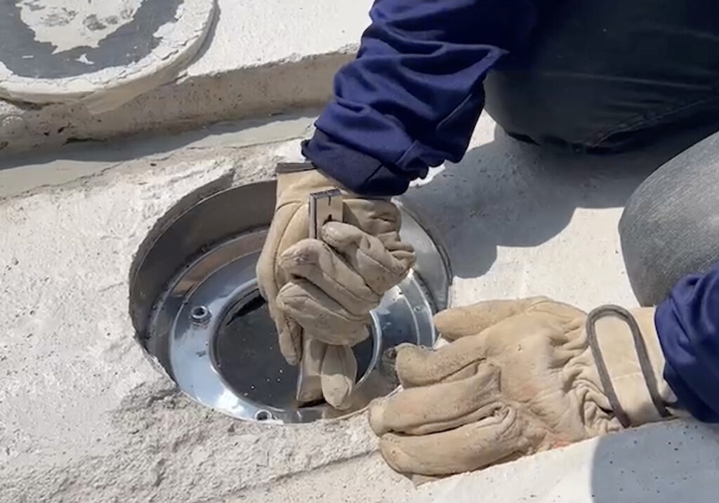
Slit the gasket out
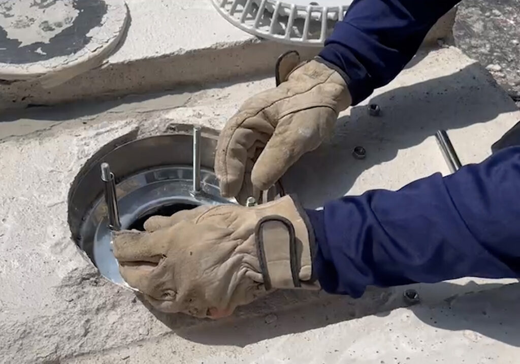
Install Stud Rod M8 and Spacer
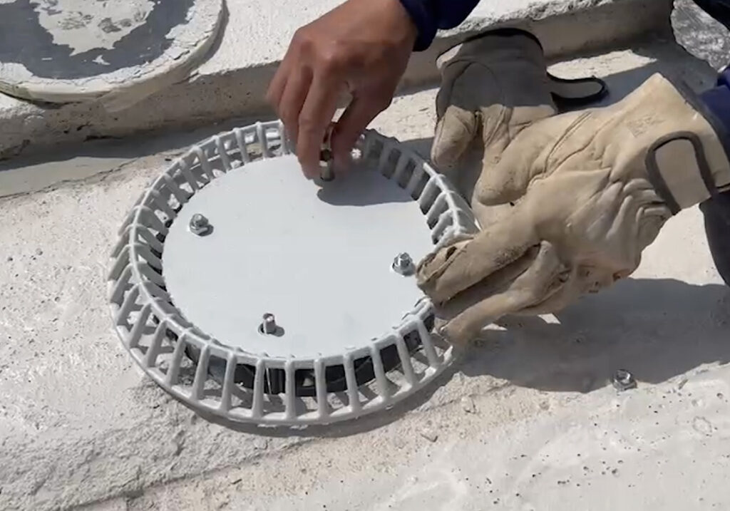
Install Anti-Vortex and tighten Nut M8
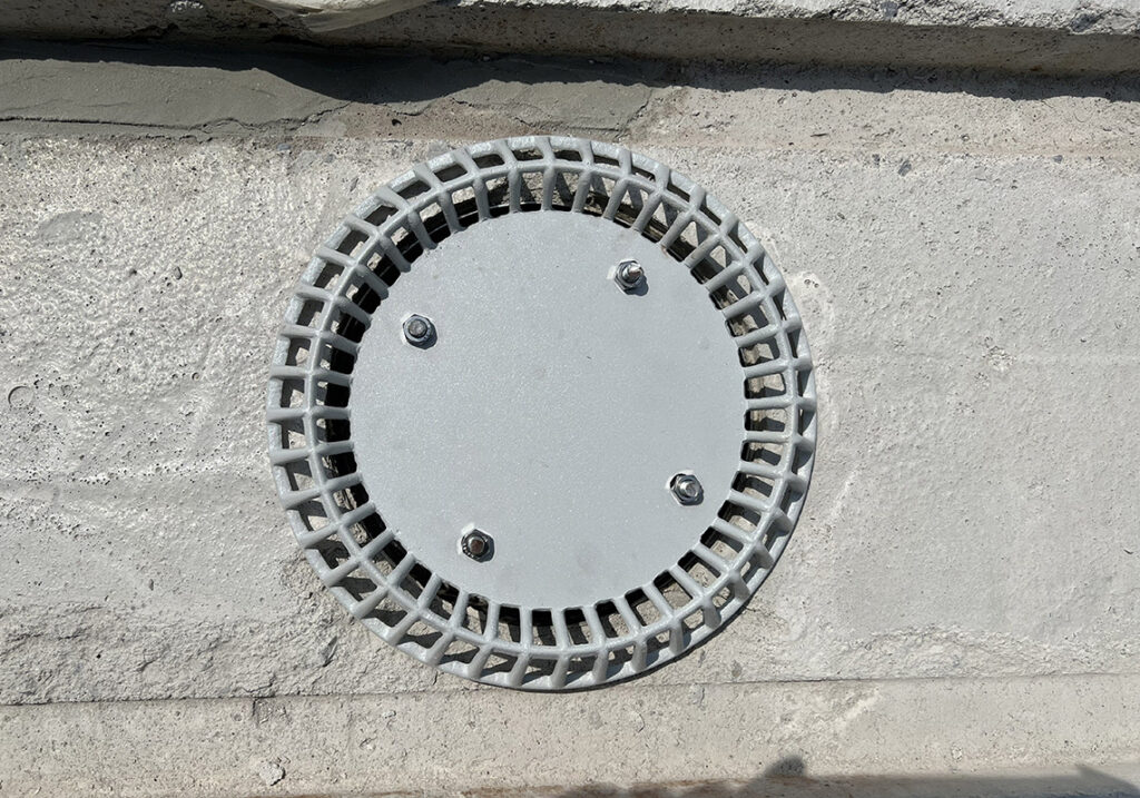
Installation complete
JAS Siphonic Rainwater Pipe Installation
The installation of JAS Siphonic system pipe must be installed in accordance with ISOMETRIC Drawing created by design engineers. The ISOMETRIC drawing will indicate the pipe size and pipe length based on the actual work site. In case that the actual pipe length from site work has changed or the pipework cannot be straightened according to the ISOMETRIC Drawing, the design team will re-calculate the change in pipe size and pipe length to be precisely installed in order to make the siphonic rainwater drainage function at full capacity.
An example of ISOMETRIC drawing for JAS Siphonic system pipe installation
Type: Multi-Outlets system
Pipe: HDPE
Method: Butt Fusion
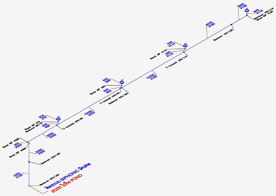
ตัวอย่าง Isometric Drawing
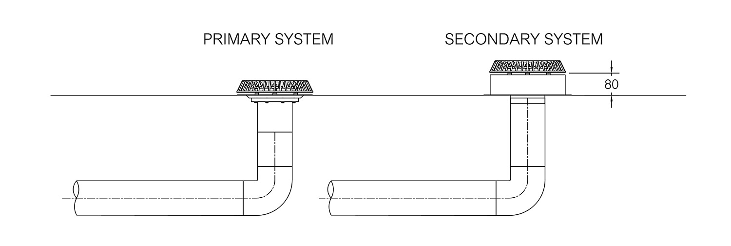
Overflow Channel Installation
at the gutter can reduce the risk of overflowing rainwater to the building due to heavier-than-usual rainfalls or clogged downpipes. The overflow channel must be installed to enhance the building’s safety,
